UML Core Elements
UML specification has the Kernel package which provides the core modeling concepts of the UML, including element, named element, namespace, relationship, directed relationship, classifier, comment, etc.
Most of these concepts are abstract, have no graphical notation, and thus not used directly on UML diagrams, but they are important for understanding of how UML is organized.
Element
Element is the abstract root UML metaclass, it has no superclass in the hierarchy of UML elements. It is the superclass for all metaclasses in the UML infrastructure library.
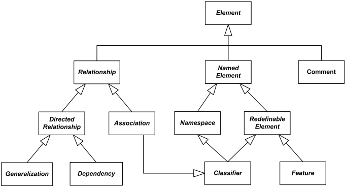
Some subclasses of UML Element
There is no general notation for an element. The specific subclasses of element define their own notation.
Ownership
UML 2.x specifications use words "owns", "ownership", "contains", "container" all over the text without providing proper explanation what those terms mean. Here's my guess about the mysterious ownership relationship.
Each UML element has a composition relationship to itself to support the capability for elements to own other elements.
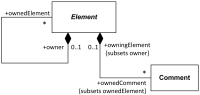
Each UML element has composition to itself
- it could own other elements.
Thus, each UML element could be an owner of other elements as defined by composition relationship - whole/part binary relationship which requires each part to be included in at most one composite (whole) at a time, and if a composite (whole) is deleted, all of its composite parts are also deleted. (UML also allows in some cases for the part be removed from a composite before the composite is deleted, and thus not be deleted as part of the composite.)
Note, that any UML element may not directly or indirectly own itself.
When UML specification defines a namespace, it says in one place that the namespace "contains a set of named elements" while in the other - that it "can own other named elements". From that we can draw a conclusion that - at least for the namespaces - ownership and containment are close to be synonyms (but most likely element that is contained is not necessarily owned).
Named Element
Named element is an abstract element that may have a name. The name is used for identification of the named element within the namespaces in which it is defined or accessible.
UML specification allows named element to be anonymous, i.e. to have no name. Also, the absence of the name is considered to be different from the element having empty name.
A named element could also have a qualified name that allows it to be unambiguously identified within a hierarchy of nested namespaces. Qualified name is constructed from the names of the containing namespaces starting at the root of the hierarchy and ending with the name of the named element itself and separated by "::". If element has no name or one of the containing namespaces has no name, then element has no qualified name.
Named element could have a visibility. Visibility defines namespaces where the named element is visible or accessible. If a named element is not owned by any namespace, then it does not have a visibility.
Some subclasses of the named element are:
Redefinable Element
A redefinable element is an abstract named element that, when defined in the context of generalization of a classifier, can be redefined more specifically or differently in the context of another classifier that specializes (directly or indirectly) the context classifier.
The redefining element must be consistent or compatible with the element it redefines. A redefinable element may be redefined multiple times. Also, one redefining element may redefine multiple inherited redefinable elements.
UML provides no notation for a redefinable element. Specific subclasses of the redefinable element define their own notation.
Redefinable element has boolean attribute isLeaf which indicates whether it is possible to redefine the element in subclasses. If the value is true, then it is not possible to further redefine the element. In Java language it corresponds to the final class, in C# - to the sealed class.
In previous versions of UML, a leaf class was shown with the property "{leaf}" below the class name. (The presence of a keyword for a Boolean type without a value implies the value true.)
In UML 2.3 the metaattribute isLeaf has been replaced by isLeaf property of redefinable element but the specification provides no notation for the elements having this property as true.
Some subclasses of redefinable element are:
Type
Type is an abstract UML metaclass which represents a set of values and is used as a constraint on the range of values represented by associated typed element. A typed element that has this type is constrained to represent values within the set of values. A typed element with no associated type may represent values of any type.
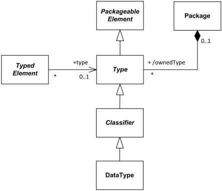
Type is UML metaclass used as a constraint on the range of values
represented by associated typed element.
Both type and typed element are abstract UML metaclasses and have no notation.
Feature
Feature represents a structural or behavioral characteristic of a classifier or of instances of classifiers.
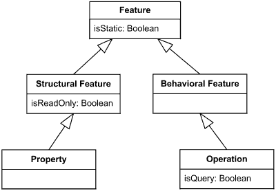
Feature overview diagram
Feature could be either non static feature or static feature. The same feature cannot be static in one context and non static in another.
Features of a class are attributes (structural features) and operations (behavioral features).
Features have no general notation. Subclasses define their specific notation.
An ellipsis (...) as the final element of a list of features indicates that additional features exist but are not shown in that list.
Non Static Feature
Non static feature characterizes individual instances of classifier.
Static Feature
Static feature represents some characteristic of the classifier itself.
Static feature could have one of two alternative semantics:
- different values for different featuring classifiers, or
- the same value for all featuring classifiers.
Because of this, inheritance of values for static features is permitted but not required by UML 2.
Names of static features are underlined.
Structural Feature
A structural feature is a typed feature of a classifier that specifies the structure of instances of the classifier, it specifies that instances of the featuring classifier have a slot whose value or values are of a specified type.
A property is an example of structural feature.
Structural feature supports multiplicity that specifies valid cardinalities for the collection of values associated with an instantiation of the structural feature.
Structural feature could be denoted as read only feature. A read only structural feature is shown using {readOnly} as part of the notation for the feature.
Structural features are not read only by default, but at the same time UML specification allows to suppress {readOnly} annotation on UML diagrams. If {readOnly} was suppressed, it is not possible to determine whether static feature is read only or not from the diagram.
Behavioral Feature
A behavioral feature is a feature of a classifier that specifies an aspect of the behavior of its instances. A behavioral feature specifies that an instance of a classifier will respond to specific requests by invoking behavior.
An operation is an example of behavioral feature.
The list of owned parameters describes the order, type, and direction of arguments that can be given when the behavioral feature is invoked or which are returned when the behavioral feature terminates. A behavioral feature may raise an exception during its invocation.
Instance and Instance Specification
Instance is some system entity, concrete manifestation (implementation) of an abstraction. Abstraction could be represented by one or more classifiers or no classifiers at all. We typically use/have instances of:
When instance manifests some classifier, it is called instance of that classifier, e.g. instance of the Customer class, Server node instance, instance of the Buy Ticket use case. In some cases, instances of classifiers have specific names. For example, object is an instance of a class, while link is an instance of an association.
Instance usually takes up some space or memory slots in the real or software world, and it could be in some state as a result of applied operation(s).
An instance specification is UML packageable element that represents some instance in a modeled system.
Instance specification is usually shown on instance level diagrams - object diagrams, composite structure diagrams, instance level deployment diagrams, on behavior diagrams - use case diagrams, interaction diagrams, and activity diagrams.
Instance specification describes instance with appropriate degree of details, either partially or completely. The description may include:
- Type of the entity, specified by none, one or more classifiers of which the entity is an instance.
- Definition of values of structural features of the entity.
- Specification of how to construct, derive, or compute the instance.
Not all structural features of all classifiers of the instance specification need be represented by slots, in which case the instance specification is a partial description.
Instance could have a name or be anonymous when name is not important. Instance name allows to distinguish the instance from other instances within the same naming context (scope).
UML 2.4 provides neither syntax BNF rules nor even verbal rules for instance names. There are as well just a few examples. It is common for the name to be a short noun or noun phrase, a sequence of letters, digits, and some punctuation marks (e.g. colon is usually excluded). I made up some BNF below, because there are some other things to keep in mind.
instance-specification-name ::=
[labels]
[instance-name] ':' [composite-type-names]
labels ::=
'«' label [ ',' label ]* '»'
label ::=
keyword | stereotype
instance-name ::= identifier
composite-type-names ::=
composite-type-name [ ',' composite-type-name ]*
composite-type-name ::=
namespace [ '::' namespace ]*
namespace ::= identifier
An instance specification uses the same notation as classifier. Name is shown as an underlined concatenation of the instance name (if any), a colon (':') and classifier name(s). Note, that the BNF above makes ':' in instance specification name required, which is not necessarily true. In some cases, when it is obvious that diagram shows an instance, it is allowed not to use underlining.
Names are optional both for instance specifications and for UML classifiers.

Anonymous instance of the Customer class.
In some cases, classifier of the instance is unknown or not specified. When instance name is also not provided, the notation for such an anonymous instance of an unnamed classifier is simply underlined colon - :.

Instance newPatient of the unnamed or unknown class.
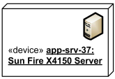
Instance app-srv-37 of the Sun Fire X4150 Server stereotyped as device.
Instance could have instance name, classifier and namespace (package) specified, all optional. The convention for showing multiple classifiers is to separate their names by commas.

Instance front-facing-cam of the Camera class
from android.hardware package.
If an instance has some value, the value specification is shown either after an equal sign ('=') following the instance name, or without the equal sign below the name.

Instance orderPaid of the Date class
has value July 31, 2011 3:00 pm.
Slots are shown as structural features with the feature name followed by an equal sign ('=') and a value specification. Type (classifier) of the feature could be also shown.

Instance newPatient of the Patient class
has slots with values specified.
Relationship
Relationship is an abstract element which represents a concept of some kind of relationship between UML elements.
A relationship references one or more related elements.
There is no general notation for a relationship. In most cases the notation is some kind of a line connecting related elements. Specific subclasses of the relationship define their own notation.
Subclasses of relationship are:
Semantic Relationship?
Though UML specifications (UML 1.3 to UML 2.4) use term semantic relationship in few places, they provide neither definition nor explanation of the term. There is no glossary in UML specifications since UML 2.0, so we may only guess meaning of many fancy terms UML specifications use.
UML 1.x categorized association, constraint and dependency as a semantic relationship. UML User Guide book at about the same time defined association as a structural relationship.
Since UML 2.0, only association is still categorized as semantic relationship by UML specification, while constraint became packageable element and dependency is now supplier/client relationship. IBM/Rational website defines association as both structural and semantic relationship where "semantic" means that there could be "connections among ... instances" and "structural" - that "objects of one thing are connected to objects of another thing". Try to find a difference, assuming objects and instances are synonyms!
My gut feeling tells me that structural relationship is relationship between whole and a part or possibly beween parts of the same whole, as for example, engine is structurally related to the car. I don't think that connected instances are necessarily structurally related. My wireless mouse has a link to my computer but it is not structural part of that computer. On the other hand, structural relationship could mean simply a relationship used on the structure diagram.
I could guess that semantic relationship is a relationship where there is some nonmaterial association or link (in common sense) between objects, without having any physical links - as a car could be semantically related to car company producing it or a player to the team he plays for - but we'll need to wait on UML authors either to stop using decorative words irresponsibly or to explain themselves properly.
Directed Relationship
A directed relationship is an abstract relationship between a collection of source elements and a collection of target elements.
There is no general notation for a directed relationship. In most cases the notation is some kind of line drawn from the source(s) to the target(s). Specific subclasses of the directed relationship define their own notation.
Subclasses of the directed relationship are:
- generalization,
- dependency,
- include (from use cases),
- extend (from use cases),
- template binding.
Comment
A comment (aka note) is an element which represents a textual annotation (remark, comment) that can be attached to another element or a set of elements. A comment adds no semantics to the elements, but it may contain some information that is useful to a modeler or to a reader of UML diagram and which usually can't be expressed with other UML elements.
A comment can be owned by any element.
A comment is shown as a rectangle with the upper right corner bent - "note symbol". The rectangle contains the body of the comment. Comment is connected to each annotated element by a dashed line.
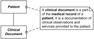
Comment explaining clinical document and its relationship to patient
The dashed line connecting the comment to the annotated element(s) may be suppressed if it is clear from the context, or not important in the diagram.