Deployment Diagrams Overview
Deployment diagram is a structure diagram which shows architecture of the system as deployment (distribution) of software artifacts to deployment targets.
Artifacts represent concrete elements in the physical world that are the result of a development process. Examples of artifacts are executable files, libraries, archives, database schemas, configuration files, etc.
Deployment target is usually represented by a node which is either hardware device or some software execution environment. Nodes could be connected through communication paths to create networked systems of arbitrary complexity.
Note, that components were directly deployed to nodes in UML 1.x deployment diagrams. In UML 2.x artifacts are deployed to nodes, and artifacts could manifest (implement) components. Components are deployed to nodes indirectly through artifacts.
Deployment diagrams could describe architecture at specification level (also called type level) or at instance level (similar to class diagrams and object diagrams).
Specification level deployment diagram shows some overview of deployment of artifacts to deployment targets, without referencing specific instances of artifacts or nodes.
Instance level deployment diagram shows deployment of instances of artifacts to specific instances of deployment targets. It could be used for example to show differences in deployments to development, staging or production environments with the names/ids of specific build or deployment servers or devices.
Some common types of deployment diagrams are:
- Implementation (manifestation) of components by artifacts,
- Specification level deployment diagram,
- Instance level deployment diagram,
- Network architecture of the system.
Manifestation of Components by Artifacts
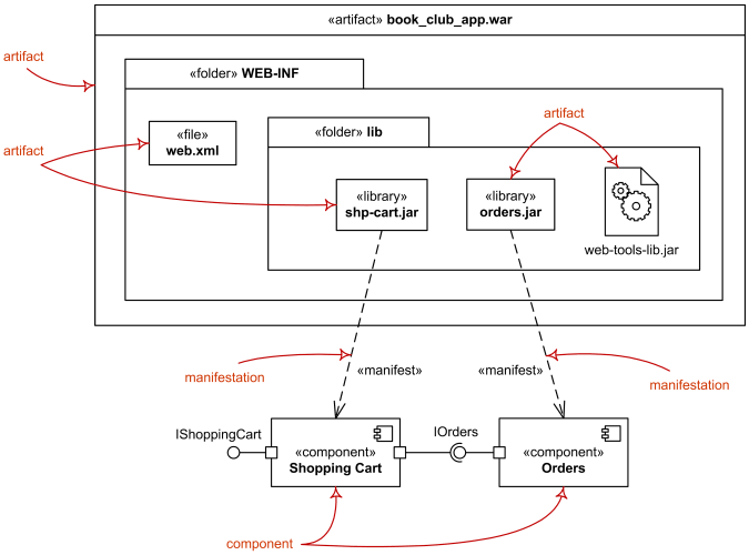
While component diagrams show components and relationships between components and classifiers, and deployment diagrams - deployments of artifacts to deployment targets, some missing intermediate diagram is manifestation diagram to be used to show manifestation (implementation) of components by artifacts and internal structure of artifacts.
Because manifestation diagrams are not defined by UML 2.4 specification, manifestation of components by artifacts could be shown using either component diagrams or deployment diagrams.

Manifestation of components by artifacts.
Specification Level Deployment Diagram
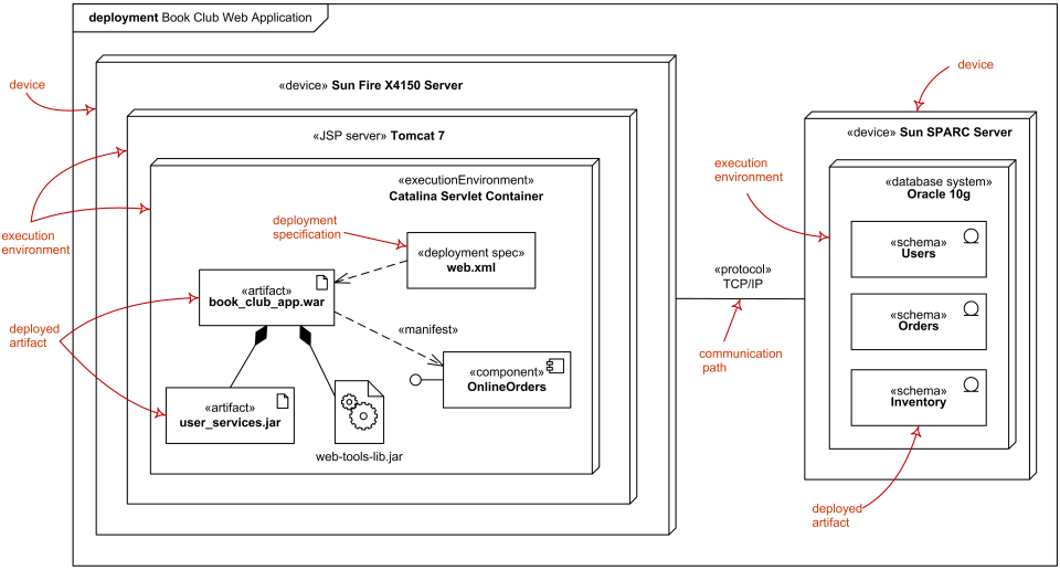
Specification level (also called type level) deployment diagram shows some overview of deployment of artifacts to deployment targets, without referencing specific instances of artifacts or nodes.

Specification level deployment diagram - web application deployed to Tomcat JSP server and database schemas - to database system.
Instance Level Deployment Diagram
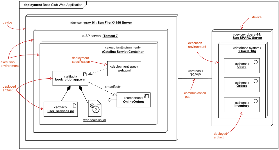
Instance level deployment diagram shows deployment of instances of artifacts to specific instances of deployment targets. It could be used for example to show differences in deployments to development, staging or production environments with the names/ids of specific deployment servers or devices.
In the example below, web application is deployed to the application server wsrv-01 and several database schemas - to the database server dbsrv-14.

Instance level deployment diagram - web application deployed to Tomcat JSP server and database schemas - to database system.
Specification Level Network Architecture
Deployment diagrams could be used to show logical or physical network architecture of the system. Network architecture diagram could show no artifacts or deployments at all or only the major ones.